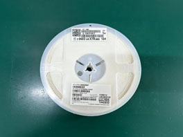
Vishay SI2325DS-T1-E3

Vishay SI2325DS-T1-E3 electronic component

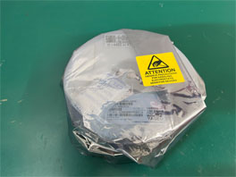
Image shown is a representation only

Manufacturer
Manufacturer No
SI2325DS-T1-E3
Date Code
2308
Quantity
24,228
Availability
In Stock
Package
SOT-23
Packaging
Tape and Reel
Description
Trans MOSFET P-CH 150V 0.53A 3-Pin SOT-23 T/R
Detailed Description
Make an effective common gate amplifier using this SI2325DS-T1-E3 power MOSFET from Vishay. Its maximum power dissipation is 750 mW. In order to guarantee safe delivery and allow for quick mounting of this component after delivery, it will be enclosed in tape and reel packaging during shipment. This device utilizes TrenchFET technology. This P channel MOSFET transistor operates in enhancement mode. This MOSFET transistor has an operating temperature range of -55 °C to 150 °C.
Datasheet
ISO 13485 certification
ISO 14001 certification
Five-Star Service certification
UKAS management certification
IAF recognition arrangement certification
HTS
COMPONENTS
PPAP
No
EU RoHS
Compliant
Category
Power MOSFET
Mounting
Surface Mount
ECCN (US)
EAR99
Packaging
Tape and Reel
Pin Count
3
Automotive
No
Lead Shape
Gull-wing
PCB changed
3
Availability
No Stock Available
Channel Mode
Enhancement
Channel Type
P
Configuration
Single
Package Width
1.4(Max)
Package Height
1.02(Max)
Package Length
3.04(Max)
Supplier Package
SOT-23
Maximum IDSS (uA)
1
Standard Package Name
SOT
Manufacturer Lead Time
42 weeks
Typical Fall Time (ns)
11
Typical Rise Time (ns)
11
Number of Elements per Chip
1
Maximum Power Dissipation (mW)
1250
Typical Gate Charge @ 10V (nC)
7.7
Typical Gate Charge @ Vgs (nC)
7.7@10V
Maximum Gate-Source Voltage (V)
±20
Typical Output Capacitance (pF)
30
Typical Turn-On Delay Time (ns)
7
Maximum Drain-Source Voltage (V)
150
Typical Gate Plateau Voltage (V)
5
Typical Turn-Off Delay Time (ns)
16
Typical Gate to Drain Charge (nC)
2.5
Maximum Gate Threshold Voltage (V)
4.5
Minimum Gate Threshold Voltage (V)
2.5
Typical Gate to Source Charge (nC)
1.5
Maximum Operating Temperature (°C)
150
Minimum Operating Temperature (°C)
-55
Maximum Continuous Drain Current (A)
0.53
Operating Junction Temperature (°C)
-55 to 150
Typical Input Capacitance @ Vds (pF)
340@25V
Typical Reverse Recovery Charge (nC)
90
Maximum Drain-Source Resistance (mOhm)
1200@10V
Maximum Gate-Source Leakage Current (nA)
100
Maximum Positive Gate-Source Voltage (V)
20
Maximum Pulsed Drain Current @ TC=25°C (A)
1.6
Typical Drain-Source Resistance @ 25°C (mOhm)
1000@10V|1050@6V
Maximum Power Dissipation on PCB @ TC=25°C (W)
1250
Typical Reverse Transfer Capacitance @ Vds (pF)
16@25V
Maximum Continuous Drain Current on PCB @ TC=25°C (A)
0.53
Maximum Junction Ambient Thermal Resistance on PCB (°C/W)
166
AttributeValue
HTSCOMPONENTS
PPAPNo
EU RoHSCompliant
CategoryPower MOSFET
MountingSurface Mount
ECCN (US)EAR99
PackagingTape and Reel
Pin Count3
AutomotiveNo
Lead ShapeGull-wing
PCB changed3
AvailabilityNo Stock Available
Channel ModeEnhancement
Channel TypeP
ConfigurationSingle
Package Width1.4(Max)
Package Height1.02(Max)
Package Length3.04(Max)
Supplier PackageSOT-23
Maximum IDSS (uA)1
Standard Package NameSOT
Manufacturer Lead Time42 weeks
Typical Fall Time (ns)11
Typical Rise Time (ns)11
Number of Elements per Chip1
Maximum Power Dissipation (mW)1250
Typical Gate Charge @ 10V (nC)7.7
Typical Gate Charge @ Vgs (nC)7.7@10V
Maximum Gate-Source Voltage (V)±20
Typical Output Capacitance (pF)30
Typical Turn-On Delay Time (ns)7
Maximum Drain-Source Voltage (V)150
Typical Gate Plateau Voltage (V)5
Typical Turn-Off Delay Time (ns)16
Typical Gate to Drain Charge (nC)2.5
Maximum Gate Threshold Voltage (V)4.5
Minimum Gate Threshold Voltage (V)2.5
Typical Gate to Source Charge (nC)1.5
Maximum Operating Temperature (°C)150
Minimum Operating Temperature (°C)-55
Maximum Continuous Drain Current (A)0.53
Operating Junction Temperature (°C)-55 to 150
Typical Input Capacitance @ Vds (pF)340@25V
Typical Reverse Recovery Charge (nC)90
Maximum Drain-Source Resistance (mOhm)1200@10V
Maximum Gate-Source Leakage Current (nA)100
Maximum Positive Gate-Source Voltage (V)20
Maximum Pulsed Drain Current @ TC=25°C (A)1.6
Typical Drain-Source Resistance @ 25°C (mOhm)1000@10V|1050@6V
Maximum Power Dissipation on PCB @ TC=25°C (W)1250
Typical Reverse Transfer Capacitance @ Vds (pF)16@25V
Maximum Continuous Drain Current on PCB @ TC=25°C (A)0.53
Maximum Junction Ambient Thermal Resistance on PCB (°C/W)166

Purchase & Inquiry

Placing an Order

You may place an order on DAXIN without creating an account.

Available Payment Methods

For your convenience, we accept several payment methods in USD, including PayPal, credit card, and wire transfer.

RFQ (Request for Quote)

We recommend submitting an RFQ to receive the latest pricing and inventory information for the parts you need.

Our sales team will respond to your request by email within 24 hours.

Important Notes

1. You will receive an order information email in your inbox. Please check your spam folder if you do not find the email.

2. Since inventory and pricing may change from time to time, our sales manager will reconfirm your order and notify you if any updates are needed.

Payment Method

Transaction fee is charged according to bank/payment system rules.

Shipping Method

Shipped from
Hongkong/Shenzhen warehouse
Estimated Ship Date
Oct 28, 2026 - Oct 29, 2026
Shipping Fee
Calculated based on your destination

Packages

Product before packing

Step1: Product

Product in anti-static bag

Step2: Anti StaticBag

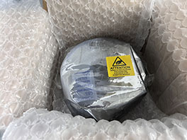
Product in individual packaging

Step3: Individual Packaging

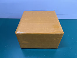
Individual packaging box

Step4: Packaging Boxes

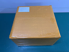
Packaging box with shipping label

Step5: Bar-Code Shipping Tags

Shipping by cargo vessel

Step6: Shipping